Desktop Lathe Project
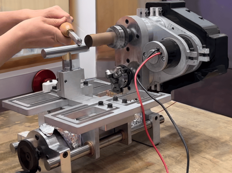
The 2.720 'Elements of Mechanical Design' class at MIT presented us with a formidable challenge: to design and build a fully functional desktop lathe within the constraints of a limited budget and provided materials. Our team of seven members set out to conceptualize, design, and fabricate this intricate machine, incorporating an electrical motor, lead screws, bolts, bearings, and other machine elements, with a set of functional requirements to meet.
Organization: Planning & Precision
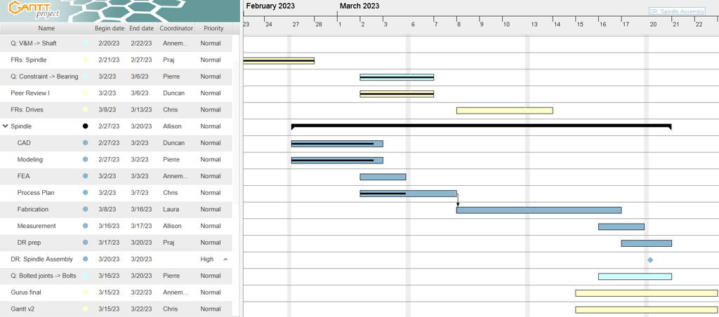
Our project's success hinged on meticulous organization and planning. We crafted a Gantt chart to map out our timelines and tasks, detailed functional requirements to guide our design process, and conducted thorough error budgeting to anticipate and mitigate imperfections in our build, inherent to the required tolerance of any manufactured part.
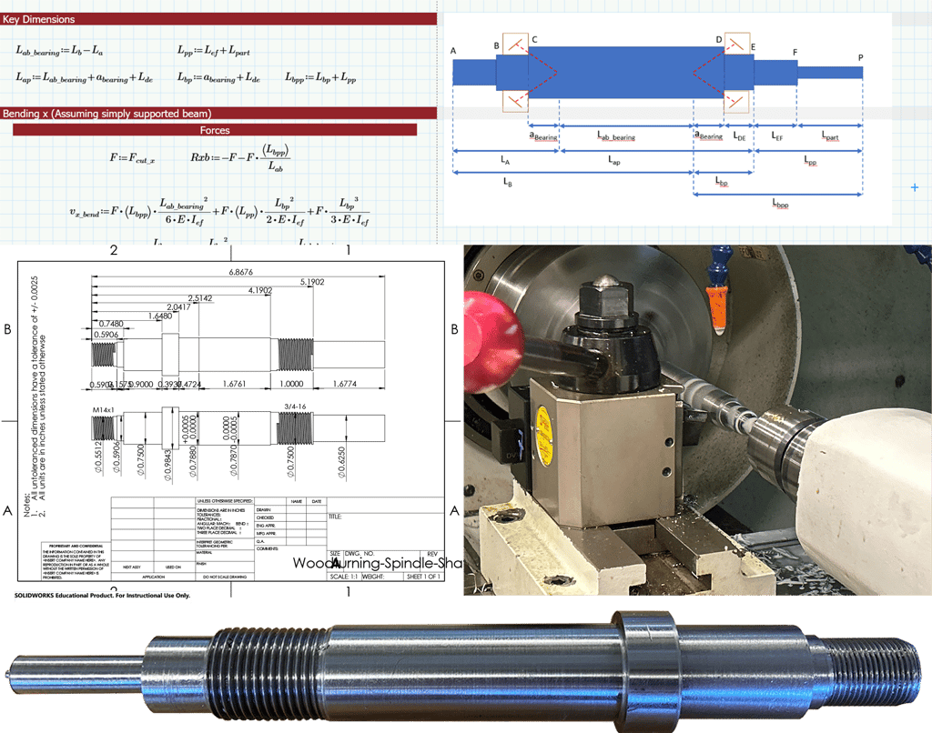
First Design & Fabrication: Spindle
The spindle was the cornerstone of our lathe design. We embarked on detailed bearing calculations and constructed free-body diagrams to ensure their functionality and reliability. As the team leader for analysis, I managed the work on this foundational component and set the stage for the rest of the lathe's structural design and operational integrity.
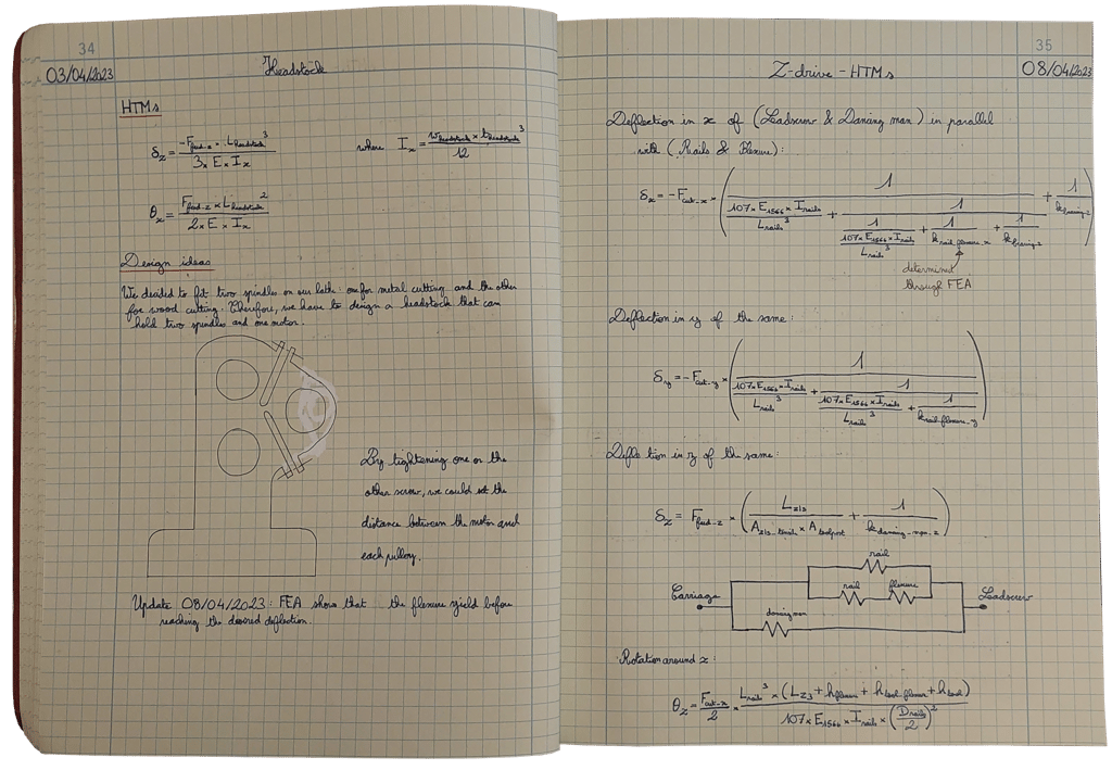
Structural Integrity and Computational Analysis
To guarantee the lathe's precision, we performed first-order calculations using Homogeneous Transformation Matrices (HTM) to model and counteract potential issues due to thermal expansion and mechanical deformation. All of our first-order calculations and verifications were recorded in an engineering notebook to keep track of our research and share it with the team. Our goal was to maintain the lathe's repeatability and accuracy under operational stresses.
Fabrication and Precision Engineering
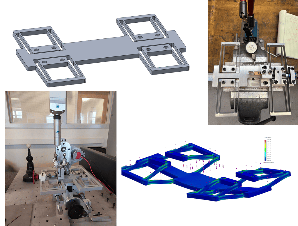
The build process involved a blend of water-jetting, milling, and turning to shape the lathe. Detailed process plans guided our fabrication steps. Complementing this, a teammate's Finite Element Analysis (FEA) on the flexures design validated our initial calculations. We then employed a Coordinate Measuring Machine (CMM) to ensure the structure's alignment and range met our precise design criteria. Finally, a series of measurements was done to ensure that we met the functional requirements, from cutting power to the actuation force.
Belt Drive System: Versatility in Material Handling
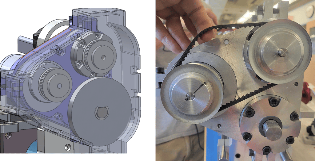
Our design included a variable belt drive system to accommodate different spindles, one for metal and the other for wood turning. The careful selection of belt profiles and system design was crucial to managing the diverse rotational speeds required by these materials while keeping a certain ease-of-use.
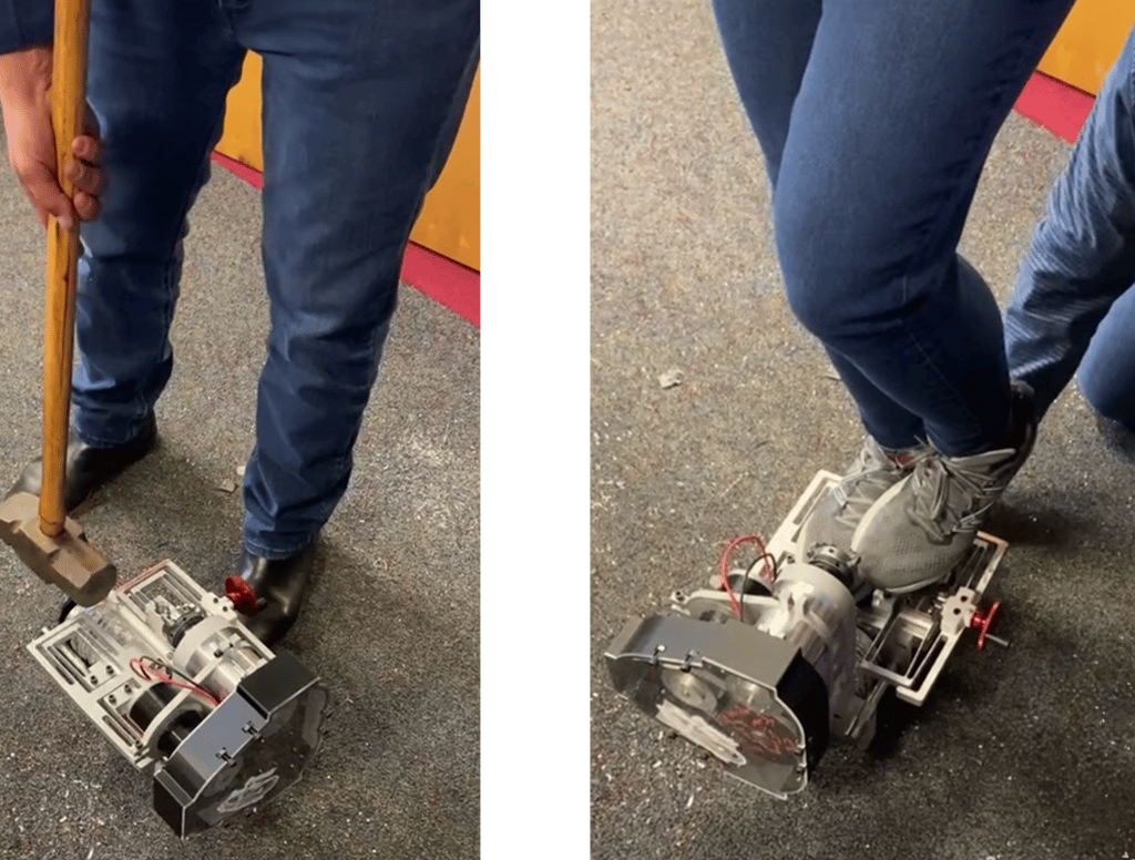
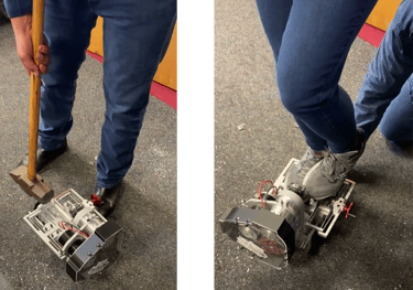
Final Presentation & Durability Testing
The project culminated with a series of rigorous tests, including drop and sledgehammer tests to verify sturdiness, and operational speed tests to confirm the machine's ease of use and precision, showcasing our commitment to quality and performance.